Chapter 1: Basics concerned with the Function and Macroscopic Species of Connectors
1.1 The Central Role of Connectors
In the automotive electrical system, along with connected between steel is far more than just “wire connector.” They fulfill multiple critical missions:
Electrical Connection and Continuity: The most basic role, creating low-resistance, stable paths for current and signals. This serves as base to guarantee the efficiency of power distribution and signal quality.
Modularity and Assembly Efficiency: As vehicles get increasingly more complex, with tens of thousands of components as we mentioned earlier. Connnectors make it possible to break down complex cable harnesses into more manageable sub-assemblies, thus greatly facilitating final assembly and making the production process more efficient.
Serviceability and Replaceability: If an electronic component (such as a sensor or ECU) fails, it can easily be replaced by simply unplugging its connector. There is no requirement to wire cut or to re-solder wires, so repair time and costs are reduced significantly.
Assembly Error Protection: Special keyways, color coding or physical construction kinetics restrict the possibility of incorrect assembly to avoid damage to equipment and safety hazard that occurs when materials are further processed with incorrectly wired manufacture.
Environmental Protection: Essential sealing, insulation and mechanical products for use in the connection point to ensure that the contact reliable operation under adverse environmen such as vibrations, humidity, temperature changes and chemical corrosion.
1.2 Macro Classification of Automotive Harness Connectors
Automobile wire connectors have a variety of designs depending on application and technical requirement. They can be roughly divided in the following dimensions:
By Electrical Performance:
Power/Supply Connectors: For use in cutting-out connections with high current transfer, may be used to connect the battery and to start up and run wires of generators, PTC-line heaters or electric compressors. Each lead has a large terminal that can conduct high currents (tens to hundreds of amperes) and is usually made of copper or a copper alloy.
Signal/Control Connectors: These are low voltage, low current connectors used for signal connections such as sensors (temp., position, R.P.M. sensors) and control units (ECU, BCM). The paramount features also focus on signal integrity and EMI immunity with finer terminals.
High-Frequency/RF Connectors: Used in GPS, radio, cellular networks and V2X communications. Necessitate special coaxial configurations for superior performance transmission of high frequency signals, where the impedance matching must be accurate (e.g. 50 Ω or 75 Ω).
By Installation Location:
Cabin Interiors: Used in the cockpit or passenger compartment where environmental conditions are less severe. Performance requirements are dominated by size, weight and cost with some degree of sealing being acceptable.
Under hood/Engine bay: Facing the harshest environment such as high temperature, humidity, vibration and oil pollution. Should have outstanding resistance to temperature, good sealing performance and good mechanical strength.
Chassis connectors: At this point it is also about water, mud, salt spray corrosi on and stone impact. Require very high mechanical protection and resistance to corrosion.
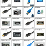
By Enclosure Type:
Wire-to-Wire Connector: For connection of two or more wires.
Wire-to-Board Terminals: Used to attach wire-in and power-out harnesses onto PCBs, highly utilized within ECUs or dashboards.
Board-to-board connectors: Connect two PCBs to one another.
Section 2: Detailed Explanation of Connector Continuation Terminating and Connecting Harnesses by Type
2.1 Types of Common Connectors and Their Structures
Top suppliers in the automotive connector market include TE Connectivity, Aptiv, Rosenberger dan Molex who all specialize in different product segments. Although having a variety of specifications, such products have similarities in their basic configuration and function principle.
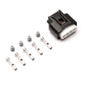
A connector typically includes:
CONNECTOR HOUSING: A structure that protects the insulation, provides guidance and alignment, support and includes mechanisms for locking and sealing purposes.
Mating Terminals: The contact to/with which the core conductive elements of the connector are to be made. These are referred to as male (posit and female (negative) terminals.
Sealing seals: Generally rubber / silicone small part plugs, gaskets which isolate the housing from water and contamination.
Secondary Locking Mechanism: Provides an added locking feature to prevent terminal from loosening under vibration or shock after engaging.
CPA: Connector Position Assurance device, which is used to validate that a connector has been fully mated and latched with its mating terminal.
Common types include:
Deutsch Series: Featuring the popular metal shell variants like the DT and DTP series, with excellent vibration resistance as well as great sealing. They are commonly utilised in rugged environments e.g. commercial vehicles, construction equipment and firewalls.
AMP Series: The Super Seal series for example These are cost effective sealed plugs, and used widely for connections to external sensors, lighting etc.
Metri-Pack Series: Designed to address engine compartment and chassis applications, providing a range of sizes (including fine pitch options) and terminal designs with balanced performance.
MQS/MCON Series: Used mainly for in-vehicle module signal transmission, emphasis on compactness and high density.
Coaxial Connectors: For instance FAKRA and H-MTD connectors are RF signal transmission optimized. FAKRA represents functions (eg blue for GPS, black is radio) using color and keyways; H-MTD is a miniaturized FAKRA with enhanced data rates that fills the gap to automotive Ethernet.
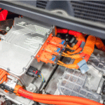
High-Voltage Connectors: As an important part of the new energy vehicles, it is primarily used to connect batteries, motor controller, DC/DC, high voltage interlock and other products. They have a unique orange color, high-voltage interlocking circuits (HVIL)and make-before-break features for safe operation.

2.2 Terminals – The Centre of Connection
The terminal point that is in contact with the electricity, and its design and materials affect the connotative electricity being connected Terminal minute site connector electrical characteristics determined.
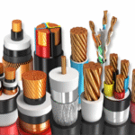
Materials: Generally include copper and copper alloys (e.g., brass, phosphor bronze, beryllium copper) because of their excellent electrical conductivity and elastic properties. In general, the surfaces experience plating for improved corrosion resistance contact resistance stabilization and wear.
Tin Plating: Low cost, good corrosion resistance, but contact resistance is unstable and micro-motion will corrode.
Gold Plating: This provides very low & stable contact resistance excellent corrosion resistance, but is expensive. Usually applied to signal connectors and sensitive low-current applications.
Silver Plating: The highest conductivity, but vulnerable to sulfidation and blackening, rises contact resistance, only for special areas of application.
Composite plating: Various layers are combined, for example localized gold over tin plating or nickel (as barrier layer) on top of a gold/tin on copper architecture, balancing performance and cost.
Types:
Stampe d Rolled-End Terminals : The Stamped Rolled-End Terminal is the most frequently used type of terminal, which can be produced by stamping method with a rolled end. They are crimped with wires by means of dedicated crimping tools. Crimp patterning is an important aspect, which needs a tight ”cold weld” seal.
Machined Terminals: Machined (or turned) to provide a more precise and stronger spring contact after the machining process. Frequently accepted to be employed where high current or high frequencies are involved.
Male Connector – Female Mating: Male terminal mating types range from common blade/ fork configurations to pin, and spring-loaded styles. Tough terminal construction with forward force provides for good, positive contact under strong vibrations.

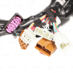
2.3 Connection of Wire Harness and Connectors
Terminals are attached to wires predominantly through:
Crimping: The most mainstream process. Individually designed tools press on the terminal’s crimping zone via which it comes to a plastic deformation and holds the conductor core in the insulation material secure. The connection made to a proper crimp should have:
Conductor crimp ter[opn zone: Provides principal electrical contact and mechanical strength.
Insulation crimp: Produces strong strain relief and a gGas- tight connection, preventing failure from conductor.
Crimp height, width and appearance are controlled within close tolerances, with verification at short intervals by a cross-section analyzer.
Soldering: Mainly for board-to-wire connections, or where wear is a concern. Provides a very low contact resistance but is complicated to perform, with the possibility of cold solder joints or solder faults. Fatigue cracks are readily formed in solder joints under vibration.
Insulation Piercing Connection: Connection method that requires no wire stripping. The terminall has a special configuration which punctures the wire’s insulation (jacket) when crimped, to accomplish electrical contact with an conductor. It has the advantage of being quick and reliable but is subject to strict requirements about precise dimensions of tools, etc.
3 Protection Methods and Material Analysis
3.1 Comprehensive Protection Methods
The demand on auto connectors is that they will be able to handle varying conditions during the course of their ‘life expectancy’ of 15 years or in excess of several hundred thousand km. Their protection is multidimensional:
Mechanical Protection:
Housing Strength: Reinforced housing provides better resistance to pressure during swings.
Locking: Primary and secondary locking prevent disconnection of terminal (terminal’s own elasticity locks) and plug connection area — CPA. Latching between connectors minimizes separation of mating.
Stress Relief: Components such as cable clamps and rubber sleeves neutralize tensile and torsional forces in the harness interface.
Environmental Sealing: (details in Section 3.3 )
Electrical Protection:
Insulation: To avoid high voltage breakdown or leakage, the air space and creepage distance between housing and terminal need to meet isolation safety standards.
EMC (Electromagnetic Compatibility): High frequency connectors can prevent external electromagnetic interference through a metal housing, also can avoid leaking of signals. A 360° connection between the shielding ring and the cable screen is essential.
3.2 Connector Materials Science
The choice of material is the basis for connector function.
Housing Materials:
PBT: Polybutylene terephthalate, the most commonly used plastic in connectors. Has excellent mechanical strength, heat resistance (long-term use at a temperature of around 130-140°C), chemical resistance, and electrical characteristics; is also highly cost-effective.
PPS: Polyphenylene sulfide has better heat resistance (up to 200-240°C) and dimensional stability but is more brittle and expensive. Widely used in high temperature environment such as engine bay.
PA: Nylon, especially PA66 has great strength and toughness. Yet, it has a higher moisture absorbance, consequently influencing its dimensional stability and dielectric properties. It is generally glass fiber (GF) reinforced.
PPA: Another glass-reinforced high-temperature nylon with properties between PBT and PPS, used as an upgraded replacement option for PBT.
Sealing Materials:
Silicone Rubber: Material of choice. Features Very wide working temperature range(-55-200°C),good elastic and sealing capabilities Aging resistant, UV & ozone resistance, available in a variety of colors with minimums. Its disadvantage: reduction of mechanical strength.
Fluorosilicone Rubber: Provides superior fuel and oil resistance compared to standard silicone rubber; supports chemicals listed in section 2, used for certain oil contact applications.
TPE/TPV: Suitable for producing integrated sealing sleeves. Although they have high efficiencies, the processing is less efficient compared to silicon at high temperature.
Material of Terminal: Like mentioned above, mainly plated copper alloys.
Sealed Design 3.3 Seal Design : Guarding Against External Corrosion
Interposed is the sealing of an external connector. Design Goal Water and dust resistance is designed for IP (Ingress Protection) level rating, eg., to achieve IP6K7 (dustproof), IP6K9K (high pressure steam cleaning)- especially, the most common application such as waterproof damp heat test of water submersion is achieved with ease by industry requirements, IPX7/IPX9K. “Sealed” usually means layered:
Interface Seal: Between mating connectors by compressing a circular crosssection seal in a groove of one housing. This constitutes the primary defense.
Cable Seal / Wire Seal: Seals moisture off from entering between the wire core or gap of wires and the housing. Typically implemented in two ways:
Sealing Gland: A rubber or silicone part with multiple holes for wire size sealing. It is slipped into place over the wires prior to crimping the terminals. Upon connecting the plugs, each wire is compressed and then released to make a secure connection.
Blind Hole Sealing Plugs: Plugged in the unused terminal hole to prevent the water, moisture or other conductive liquid from enter through the vacant cavities.
Secondary Injection Molding Seals: In high-volume connectors, a secondary injection molding process injects either TPE or similar materials into the interface between the wire harness and connector. This provides a strong, solid barrier with very high reiliancy.
Seal design is also commonly validated on a leak tester, in order to measure the ra te of leakage at a given pressure within acceptable limits.
Chapter 4: Key Factors to Consider in Automotive Wire Harness Connectors
The choice of connector for a given application is a rationalized engineering problem that weighs many trade-offs. The primary aspects of selection are:
Electrical Parameters Take Priority:
Current/Voltage: Start by looking at the maximum continuous, peak current draw, and operating voltage of your circuit. Choose the size and type of terminal as appropriate,while also taking into consideration enough safety currentcarrying capacity margin (derating should generally be chosen such that the rated current is 70-80% at best).
Number of Circuits: Know your pin count requirements now and need for future expansion to select a size that will not leave you wishing you had a few more pins.
Signal Type: Select an appropriate coaxial/differential pair connector for high frequency signals to minimize characteristic impedance, insertion loss and return loss.
Kemampuan Beradaptasi dengan Lingkungan:
Temperature: Take into account the maximum and minimum ambient temperatures at the connector’s installation site and temperature rise of the connector itself. Certain selected materials (especially units and seals) have to guarantee the long-term service life within this temperature range.
Moisture and Water Resistance: Select the right IP code protection level based on where the connector is located, then use it to pick those with matching sealing capabilities.
Chemical Environment: Will the connector be subjected to motor oil, transmission fluid, gasoline, brake fluid, antifreeze or cleaning agents? This affects the choice of material and seal.
Vibration and Shock: Choose connectors with a sturdy locking mechanism that can handle the specified levels of vibration, referring to automotive standards (such as USCAR-2).
Mechanical and Physical Requirements:
Space-limited: The actual connector dimensions in addition to mating orientation (right-angle, straight) must fit within the allotted space.
Mating Cycles: Anticipated number of times the connector will be inserted/removed during the vehicle life. This becomes especially crucial for parts that need regular maintenance or replacement.
Insertion/Extraction Force: Insertion and extraction force are consistently moderate. Too low and connections may be compromised; too high and assembly becomes difficult, the risk of damaging someone’s connector rises.
Color and Keyways: The use of color and/or physical keyways to prevent misinsertion ensures assembly accuracy.
Cost and Supply Chain:
Total Cost of Ownership: By factoring in the connector’s unit price and crimping/assembly tools, assembly time, maintenance ease, and risk costs driven by reliability must also be considered.
Standardized Product Series: Give priority to products of the same blazing series which are widely applied and with mature technology or hot sellers in market, achieving favorable compatibility and stability, facilitation for replacing at later stage.
Vendor Support: Choose suppliers with strong technical documents libraries, test reports and extensive engineering support options.
Regulatory and Standards Compliance:
Make sure the chosen connectors satisfy automotive industry and regulatory needs for the given market – requires knowledge of ISO, SAE, LV series and national automotive safety regulations.
Bab 5: Custom Automotive Wiring Harnesses— From Concept to Reality
There is a large need for not only mass-produced vehicles, but also for personalized automobile wire harnesses. PoP and AMR are typical wire types in modified vehicles, racecars or speciality vehicle (i.e. fire trucks, ambulances), RV’s and re-wiring harnesses or upgrades on older model vehicles.
The custom harness process often involves:
Requirement Analysis and Identification: This is the most essential step. It requires clarifying:
Functional Requiremets: What are the electrical duties? (e.g., installation of ancillary lighting, audio systems, power inverters, data loggers, etc.)
Power and Load Analysis: How are the power levels, operating current ratings, and surge currents for every device?
Routing Path Planning: What is the path taken by the wire and harnesses in their entire length across the body? Can hazardous locations of high temperature, moving parts, sharp edges be found?
Connection Point validation: From where the power will be sourced? Will I need another Fuse Relay box? Where does it make sense to position sensors and actuators?
Schematic Design:
Develop detailed circuit schematics with professional EDA tools (Zuken E3, Capital, or even AutoCAD Electrical).
Specify fuse sizes, relay types, wire colors and gauges, & ground locations for all circuits.
Sequential numbering to every wire and connector for production and traceability.
Component Selection:
Cables: Choose the proper gauge based on current draw of the application. Select automotive-quality wire that is temperature rated, has insulation identified as per the insulation type (e.g., cross linked poly, color coding.
Adapters: Follow the selection rules above to select the right pad array for each connection point. For custom applications, series as Deutsch or AMP Super Seal are heavily used due to modularity, availability and reliability.
Protective Materials: Choose from a variety of corrugated tubing, braided mesh tubing and tapes flannel tape, PVC tape) providing abrasion resistant, heat flame retardant protection for wiring harnesses.
Fuse/Relay boxes: Choose from various integration levels for central electrical enclosures and layout cleanliness, plus ease of maintenance.
Manufacturing and Assembly:
Wire Cutting & Marking: Cut wires to length using professional wire cutters per schematics, and print wire numbers on both sides.
Crimping: Use calibrated crimping tools to press terminals onto the ends of wires. It is the basic mechanism of electrical power reliability.
Pre-assembly: Routing and clamping of crimped wires to PCB according to branch situations.
Sealing and Terminal Installation: Insert in sequence the sealing plugs and terminals into the connector housing while inserting ensure both primary and secondary lock seat.
Wrapping: If knotting a trunk or branch, wrap trunks and branches with tape, heat shrink or similar.
Conductivity/Test: The connectors are 100% conductivity (classic fusion of high purity tin + matte finish) tested before and after thermoshaped and then inspected to ensure there are no short circuits, opens or mis-wiring by use of a special harness tester/multimeter.
Installation and Commissioning:
Mount the custom wiring harness to your vehicle, making sure that all connectors are connected and locked in place, no hanging loose or connector not fit upon the connector line side.
Boot the system up and test all of the PC’s functionality.
Custom Wiring Harnesses Benefits and Obstacles:
Advantages:
Custom Fit: Fits without having excess bulk, prevents overstretching or short…elles]CppGeneric-683728.html Design:Exact fit to vehicle layout,Can be applied to anywhere as needed.
Performance Boost: Provides dedicated power source lines for your high performance components, reduces power loss and helps to get optimal sound.
Increased Durability: Constructed with higher-grade materials than the OEM harness, for most dependable longevity.
Ease of Maintenance: The combination of clear labelling and logical routing make fault finding and repair easy.
Challenges:
Expensive: Small-scale manufacturing and design development mean your per-unit cost will be much higher than for mass- manufactured parts.
High technical requirement: Desginer has the high knowledge about technical of automotive electrical and have clear picture about connector and wiring harness production.
Long Lead Times: Great time is needed from when a design is initiated to when it turns into a final manufactured product.
Kesimpulan
Automotive wiring harnesses connecters, as small parts which are easily to be ignored, is the foundation and enabler of vehicle electric electronic architecture. From the simple electrical interface to complex sealing protection, precision material science and tough perfection with respect to systems – everything in them is a testament to technical depth. With vehicles moving toward “New Four Modemizations” (electrification, intelligence, connectivity and sharing), connectors bear greater responsibilities: voltage and power are increasing; data is being transmitted faster with automotive Ethernet; lightweighting and miniaturization are becoming bigger challenges; system security is stronger than before.
A deep-level understanding and mastery of automotive wiring harness connector technology are not only necessary for engineers in the automotive field, but it also becomes a key to enter into a more reliable, efficient, safe and comfortable automated electronics world for all staff covering every corner related to the automobile industry, even home car fans or professional relays based on the vehicle update! The connectors will remain the most dynamic and vital nodes in the automotive nerves, leading new innovations and development of automobile.
Hubungi kami segera untuk mengetahui bagaimana kami dapat memenuhi kebutuhan kabel dan harness Anda. Ikuti kami di Youtube .